Slope / Function Generator
In this post we’ll look at the design of a function generator that outputs slope waveforms with adjustable rise and fall times. This can be used in modular synthesis as an envelope, or control voltage to modulate some other parameter in your synthesiser. This post is purely electronics with no CPUs allowed on the scene.
For all the circuits and fragments in this post, I have linked to simulations you can play with. I was going to embed them, but there is no way to prevent all the simulations starting at once and killing your CPU, so I’ll leave it to your discretion :)
Intro
Recently I have been getting back into electronics and synthesisers. I do have some hardware semi-modular synths, and have been playing around with VCV Rack a lot. A module I like in particular is Befaco’s Rampage.
I find myself using this module all the time in VCV rack, and decided it would be fun to have a go a building my own lite version of it. Rampage does tons of stuff which I am certainly not trying to achieve. What I would like is the basic function generator capability with the following features (to start with)
- Triggerable function generator
- Once triggered, it will always fall once the rise has completed, even if the trigger input is still high (eg it does not sustain in any way)
- Variable rise and fall times (via potentiomenters for this design, not external control voltage)
- Retriggerable during the fall stage
- Powered with Eurorack style +/– 12v rails
- Unipolar output at 0–10v
Note I am no electronics expert, merely a hobbyist messing around a bit!
Generating Ramps
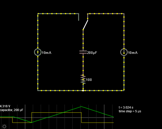
The first problem then is how to generate a ramp. If you charge a capacitor with a voltage source and some resistor, you will get an exponential voltage curve

I don’t want an exponential curve, though, I want a linear ramp. Charging a capacitor using a constant current source will achieve exactly that, and the time can be controlled by the resistance.
We can create a constant current source in a number of ways, for example with a transistor based current source circuit or an op-amp current source.
Another way to produce a linear ramp is to use an op-amp as an integrator.

In this design, the op-amp produces an output voltage proportional to the integral of the input voltage, with the feedback loop charging and discharging the capacitor. The simulation above uses a +/– 5v square wave as an input, causing the capacitor to charge and discharge through the op-amp (which can both sink and source current) as the voltage swings above and below ground. The op-amp tries to reach its maximum and minimum output values - in this simulation the op-amp is configured with +/– 15v
Bi-Directional Ramp
In order to control the rise and fall time of the wave independently, we’re going to need to somehow have the capacitor charge through one resistor, and discharge through another. The diode comes to the rescue here. Since the diode allows current to only flow in one direction, it lets us setup a one-way system depending on the direction of the flow.

Here I have used a small resistor in series with a potentiometer for each path. The small resistor exists to set a minimum resistance, whilst the potentiometer allows us the control the rise and fall times. Of course, different values of capacitor and resistors will give us different minimum and maximum slope times.
The next problem is two-fold. We don’t want the full +/– 12v range as an output - the final goal is to have 0–10v, slightly less than half of the range. Since the op-amp starts at –12v, we will aim to stop it charging once the capacitor hits 0 volts (half the voltage) at which point it should begin the discharge phase. Later we will shape this output voltage into what we want, but first we need a way of knowing when the capacitor has arrived at 0 volts, and some form of managing which state is currently active (charge or discharge).
Let’s first look at the state. We don’t have any kind of clock signal, so we need something async. The Set Reset latch is about as simple as it gets, providing us with one bit of memory that can be toggled.

This arrangement of two NOR or NAND gates with feedback stores a single bit of memory. When one of the lines go high, it will flip the state if applicable. The SR latch is essentially a flip-flop without the clock signal. It does have some issues though, notably it might not respond well to an invalid input state (eg, both inputs high).
A requirement was that once a trigger arrives, the rise time should always complete, and then during the fall time a signal may re-trigger the process. Another requirement was that the fall cycle should always happen, even if the trigger signal is still high.
The SR latch already deals with the first - subsequent pulses to the latch will have no effect until it has changed to its other state.
The second we can deal with by ensuring that when a trigger signal arrives, we only take a tiny pulse of it and block the rest. This circuit is called an edge detector, and there’s various ways to achieve it.

Capacitors block DC voltage once they are charged. This simple circuit (also known as a high-pass filter) will pass a small amount of current until the capacitor is charged, at which point it stops conducting. The result of this is that the logic gate will see a pulse that’s long enough to trigger it, and nothing else until the input signal cycles from low to high again.
The latch is comprised of logic gates that are not designed to source and sink current with negative voltages. Instead, we’ll feed its outputs into our friend the op-amp. When used like this, the op-amp acts as a comparator (we’ll see this shortly). Depending on which side is high its output will be driven to +/– 12v.
Putting all this together will give us a circuit which we can manually trigger the SR latch and cause the circuit to charage and discharge the capacitor.
Auto Reset
All we need now is a way to send a signal to the latch when the capacitor reaches 0 volts. The op-amp provides us the solution with the comparator configuration we used earlier. In this case we simply provide a reference voltage (0v, ground) and feed the output of the integrator to the other input. Now, when the voltage reaches zero, the comparator will flip to high. We can feed this signal into the SR latch, causing the reset phase to begin.

Output stage
All that remains is to shape the output into 0–10v. Currently we have –12–0v, so first we’ll simply add 12v, bring the output into the positive range. To achieve this, the op-amp is back on the scene, this time in its non-inverting summing configuration

Now we are left with a signal from 0–12v, we can divide this voltage proportionally using a simple voltage divider. Since the power supplies and op-amps used might not be perfect, we could use a precision potentiometer here so the user can tune the signal to exactly 10v.
Real World
Simulations are all well and good, but they don’t reflect the real world with non-perfect components. If you play with the simulations above, you will notice sometimes the flip-flop gets stuck in an oscillating state. This is because the simulation is TOO perfect!
I have built the circuit as above using an LF444 op-amps and a D-Type flip-flop in its “active” mode instead of the NOR gates.
In the picture below you can see the output waveform at its pre-final stage where it is still inverted. The trigger input is being fed with a pulse generator. You can see that subsequent pulses during the fall stage cause re-triggering as we wanted.


I will be adding more features to this before putting onto a more permanent board. Possible features include
- Two independent function generators
- Ability to output +/– 5v bipolar control voltage via a switch
- Control voltage inputs for the rise and fall times
- Different minimum/maximum time periods via a switch
- A loop switch that will cause the ramp to automatically re-trigger, so it can be used as an LFO or oscillator
- Other comparison based modulation outputs, like Rampage does.
- Protection circuitry to defend against the unpredictable outside world.
- etc